


 135 / 5157

Nexon Gasoline – EMS ECU Bosch
DTC Troubleshooting Manual
Version: 0.1
Date: 26-08-2017
Prepared By: Sunu S Babu/Yogesh Jadhav
Checked By: Yeshwant Jadhav
Approved By: Satish Kumar
Document Part No: 2921 02 224 A1736
Page: 131 of 1203
Copyright ©
TATA MOTORS Ltd.
This document must not be used in any way, such as copying and redistributing to third parties, without the consent of author.
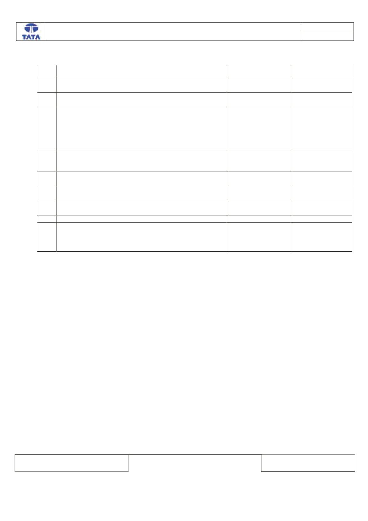
Trouble Shooting:-
Step Checks
IF YES
IF NO
1.
Is the Inlet Air Circuit Clogged
Rectify / Replace the
Air inlet Circuit
Go to Step 2
2. Is there any rust/oxidization observed on Sensor Terminals Clean the Rust or
repair or replace
Go to Step 3
3. Is there wiring harness electrical continuity between ECU
pins 103, 125, 112 & TMAP Sensor connector pins 1, 3, 4. Go to Step 4
Establish continuity
by rectifying
harness
connections as per
the Circuit
schematic
4
Are there any pins damaged at Sensor/EMS ECU
Connector
Replace the
connector or wiring
harness
Go to step 5
5
Are there any pins backed out from the Sensor/EMS ECU
Connector
Rectify/Replace
Connectors
Go to Step 6
6
Is Sensor Supply pin 125, Short Circuited to GND/Battery
Repair the harness
as per the schematic Go to Step 7
7
Is Sensor Signal Pin 112, Short Circuited to GND/Battery
Repair the harness
as per the schematic Go to Step 8
8
Is Sensor physically Damaged
Replace Sensor
Go to Step 9
9
Fault Still Persists?
Replace Sensor and
then Fault still
persists then
Replace EMS ECU
Follow the steps
again for
reconfirmation
DTC’s confirmation:-
After rectification, ensure the following points by referring engine parameters using TML diagnostic tool before
handing over to customer.
1. Boost pressure value reads by the ECU is = Atmospheric pressure at ignition key is on.
2. Boost pressure value reads by the ECU is < Atmospheric pressure when the engine is at idle.
3. Boost pressure value reads by the ECU is > Atmospheric pressure when the engine is at fly-up.