


 4464 / 5157

Copyright ©
TATA MOTORS Ltd.
This document must not be used in any w ay, such as copying and redistributing to third parties, w ithout the consent of author .
SRS / Airbag
ECU – DTC Troubleshooting Guide
Version: 14.0
Date: 14-February-2017
Prepared by:Airbag COC Review &
Approved by:Sanjeev VM
Page: 392 of 549
DTC’s confirmation:-
After rectification, ensure the following points using TML diagnostic tool before handing over to customer.
e)
Clear the DTC’s & make sure no DTC’s are present for Airbag system
f) Check whether a
ny new DTC’s are getting qualified for repeated cranking.
g) Ensure the Airbag Warning Lamp Indication is continuously ON in Instrument Cluster for
4 seconds
after
Ignition ON
h) Ensure the Airbag Warning Lamp Indication goes OFF after
4 seconds
from Ignition ON.
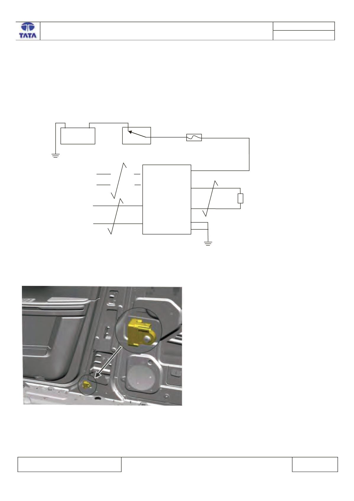
Circuit Schematic Diagram:-
Schematic shown below for illustration
Battery>>>>>Fuse>>>>Relay>>>>>>>Sensor/Actuator>>>>>ECU
Component Location & Image:-
Fig 351:Driver side peripheral sensor
+
V
12
Battery
A23
CAN H
Ignition Sw itch
CAN L
A12
A7
-
RESTRAINTS
CONTROL
MODULE
A1
A2
Fuse 10A
B9
DSPS+
Vbat
B10
DSPS-
Driver Side
Peripheral Sensor