


 4661 / 5157

/ŵŵŽďŝůŝnjĞƌ ʹ d dƌŽƵďůĞƐŚŽŽƚŝŶŐ ĂƚĂ
sĞƌƐŝŽŶ͗ ϭ͘
2
ĂƚĞ͗
03-June-2014
Prepared Author
:
0LWKLSDWL 3UDVDG
Review & approved by
: R A Rode (ERC-E&E)
Page: 34 of 67
Copyright ©
TATA MOTORS Ltd.
This document must not be used in any way, such as copying and redistributing to third parties, without the consent of author.
DTC’s confirmation:-
After rectification, ensure the following points before handing over the system to the customer
4) Battery Voltage is between 9 to 16V.
5) Replacement of ECU
6) Drive the vehicle on road and check the assistance.
Circuit Schematic Diagram:-
9,&0
SLQ
QR
3LQ GHVFULSWLRQ
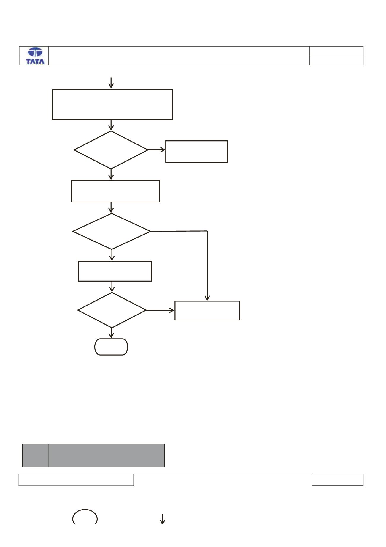
A
Stop
Yes
No
Is voltage <
13.5v?
Replace/ Recharge
the battery
Take corrective action to
repair alternator circuit.
No
Yes
Is DTC
Present?
Check whether under bonnet fuse box
(60 Amp) is blown off.
(Circuit
Schematic Diagram)
Is Fuse
blown off?
Yes
No
Replace the
respective fuse
Check the Alternator output
voltage.