


 4678 / 5157

/ŵŵŽďŝůŝnjĞƌ ʹ d dƌŽƵďůĞƐŚŽŽƚŝŶŐ ĂƚĂ
sĞƌƐŝŽŶ͗ ϭ͘
ĂƚĞ͗
03-June-2014
Prepared Author
:
6DUDQJ . 0LWKLSDWL 3
Review & approved by
: R A Rode (ERC-E&E)
Page: 51 of 67
Copyright ©
TATA MOTORS Ltd.
This document must not be used in any way, such as copying and redistributing to third parties, without the consent of author.
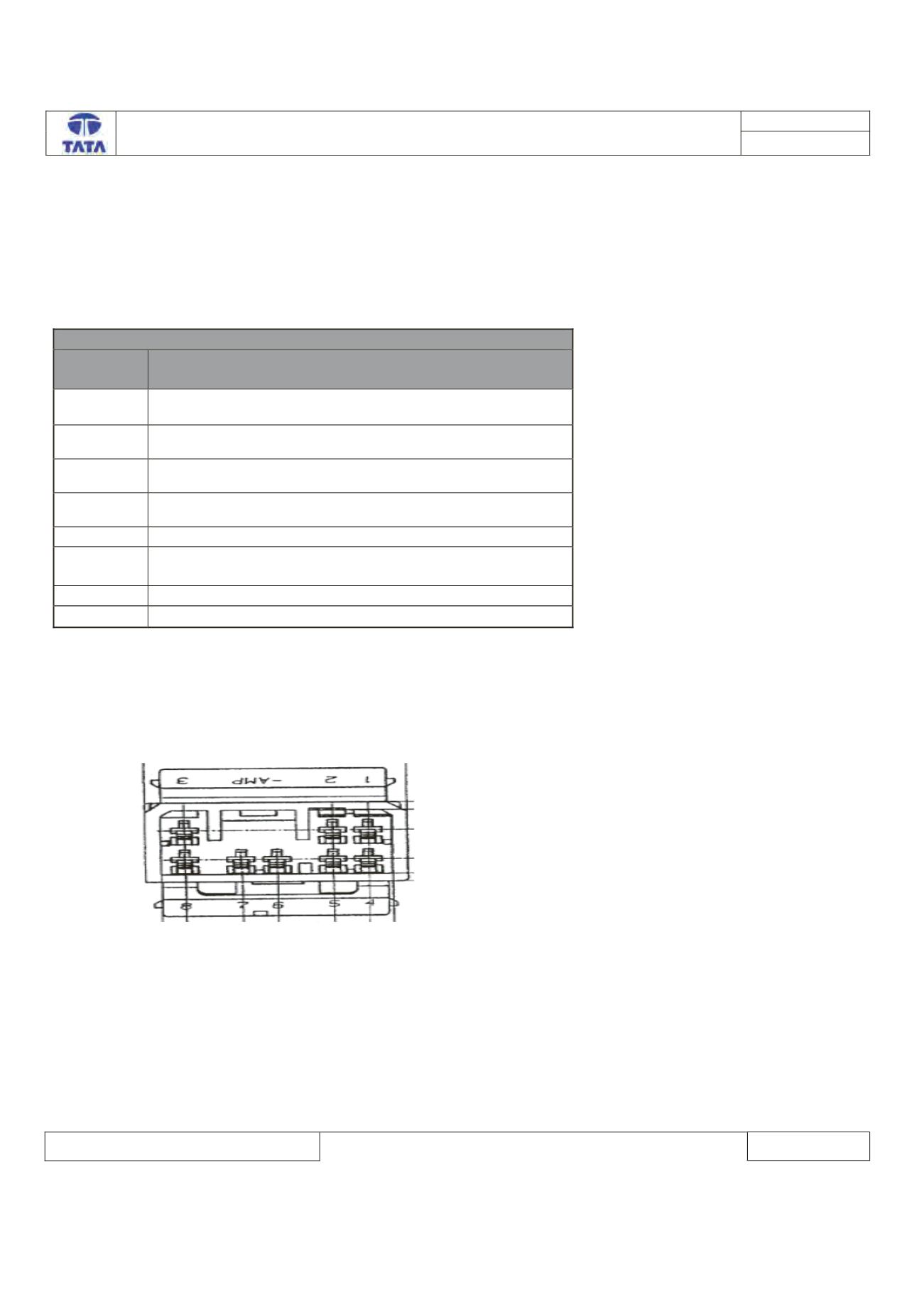
Connector View & Information: -
VICM ECU connector side diagram: -
Conti VICM Pin Details
VICM
pin no
Pin description
1
Vbatt (KL30)
2
GND
3
CAN_H(High-speed)
4
Ignition (KL15)
5
Status LED
6
Lock set Illumination (not used if incase of BCM not
connected)
7
Battery Supply (+Vbatt)
8
CAN_L(High-speed)
VICM connector view: -
ECU side: -
Inspection Method: - N.A