


 518 / 5157

Nexon Gasoline – EMS ECU Bosch
DTC Troubleshooting Manual
Version: 0.1
Date: 26-08-2017
Prepared By: Sunu S Babu/Yogesh Jadhav
Checked By: Yeshwant Jadhav
Approved By: Satish Kumar
Document Part No: 2921 02 224 A1736
Page: 514 of 1203
Copyright ©
TATA MOTORS Ltd.
This document must not be used in any way, such as copying and redistributing to third parties, without the consent of author.
Sensor Standalone diagnosis data:-
Crank Sensor
Crank angle Sensor provides engine speed and crank angle input to ECU. 58 teeth are spaced at an angle of 60 each
on the flywheel and two teeth missing at 1140 ATDC (Top Dead Centre) of cylinder 1 allows the piston position to be
determined. Crank angle Sensor is positioned on this teeth, so that an AC voltage is induced in Sensor coil, when the
Flywheel tooth projection passes through the Sensor. The AC voltage is proportional to thespeed of rotation.The
Sensor is mounted in the engine compartment. It is used for the detection of the crankshaft position and speed. The
Sensor detects the slots and teeth of a ferromagnetic target wheel anddelivers an electrical signal according to the
movements of the target wheel. Therefore the signal Represents the speed and position of the crankshaft. Proper
function of the Sensor can only be covered, if the specified mating connector is properly assembled. All wire seals
have to be in place. With an unsealed connector the Sensor will not be waterproof.
Crank angle Sensor is an inductive type 3 pin connector, is mounted on cylinder block over the flywheel.
Sensor gap to be maintained -: 1.5 ± 0.75 mm Mount the Sensor using a suitable bracket and tighten the bolt to the
specified torque.
Operating Principle:
Due to the rotation of a ferromagnetic target wheel in front of the DG the magnetic field of a magnet
is modulated at the place of a coil, i.e. with a tooth in front of the DG the magnetic flux through the coil will increase,
with a slot it will decrease. This modulation results in changes of the output signal/voltage. The change of the
magnetic field causes magnetic induction in a coil by variation of the magnetic flux.
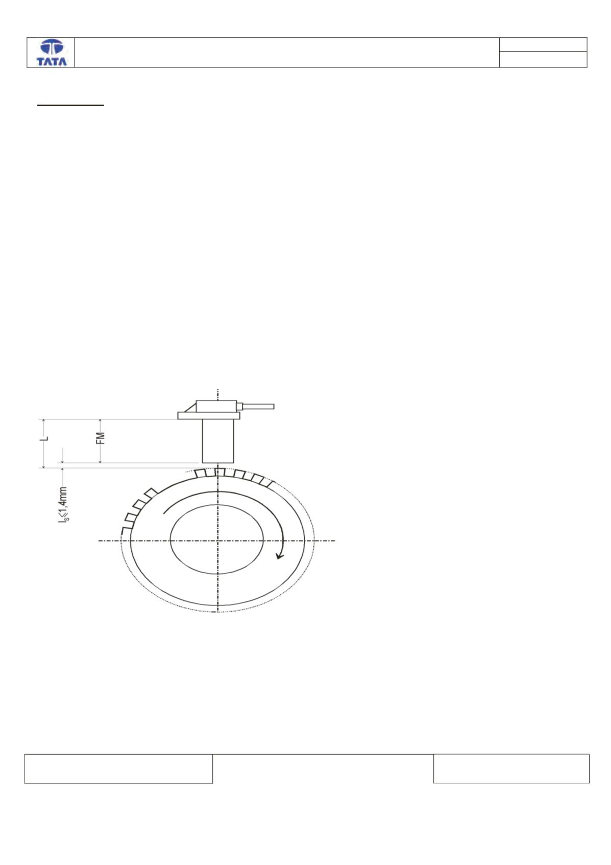
Working Air Gap and Installation Dimension
Minimum working air gap LS,min = 0.3 mm
Maximum working air gap LS,max = 1.5 mm