


 1835 / 5157

OSPREY- Application
DTC Troubleshooting Data
Version: 4.0
Date: 10-02-2017
Prepared by: Mithipati Prasad
Checked by: G S Raju / Senthilnathan S
Page: 624 of 654
Copyright ©
TATA MOTORS Ltd.
This document must not be used in any way, such as copying and redistributing to third parties, without the consent of author.
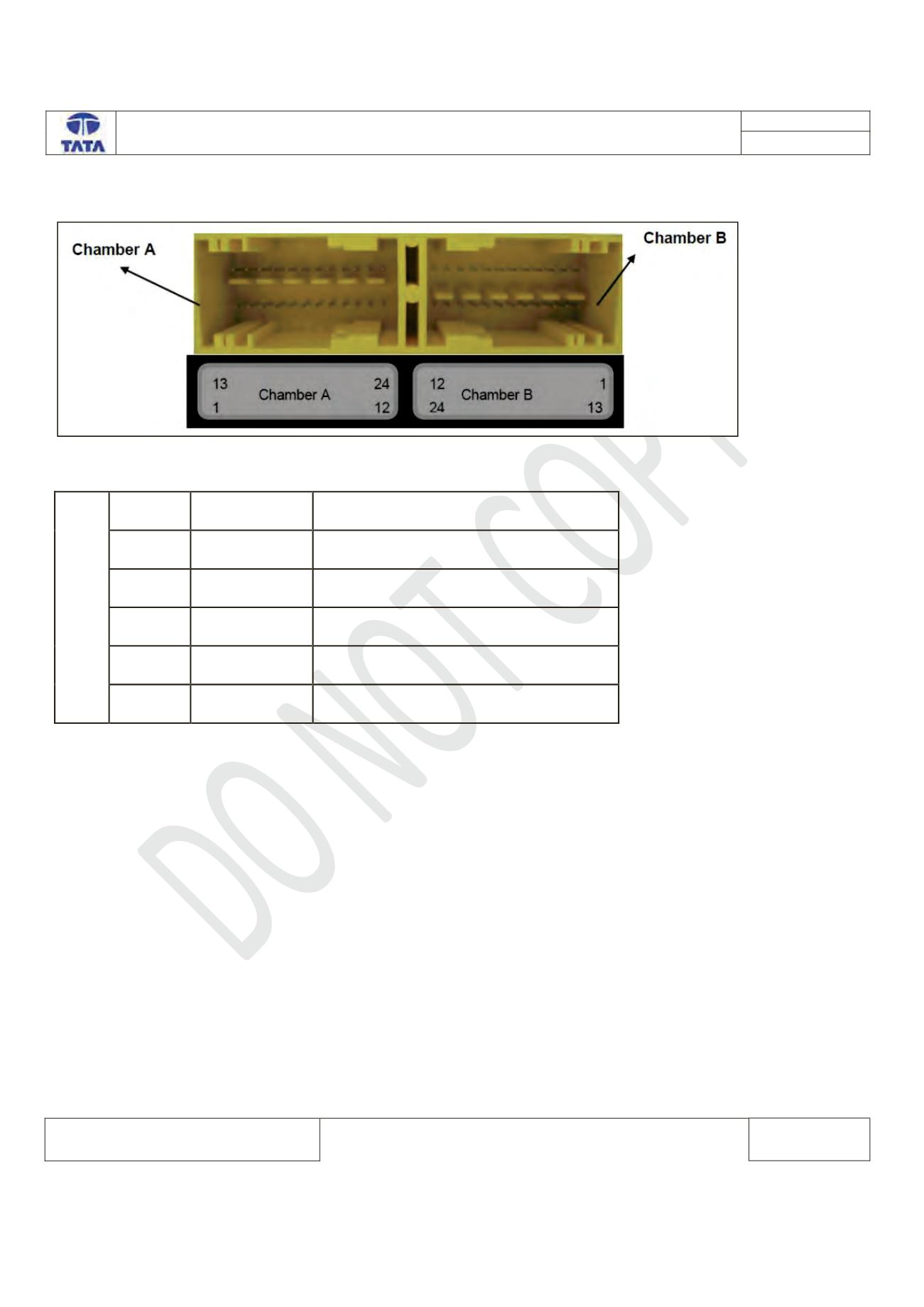
RCM ECU Connector Details
RCM ECU side connector diagram
RCM ECU Pin assignment:-
CHAMBER A
Pin No.
Pin Name
Description
1
CAN_H
CAN High
2
CAN_L
CAN Low
7
A_GND
Common Switch GND
12
IGN
Supply Voltage Battery
23
GND
Power GND