


 1891 / 5157

yϭϬϰ KƐƉƌĞLJ /ŶƐƚƌƵŵĞŶƚ ůƵƐƚĞƌ
d dƌŽƵďůĞƐŚŽŽƚŝŶŐ ĂƚĂ
sĞƌƐŝŽŶ͗ ϭ͘ϯ
ĂƚĞ͗ ϮϬͲDĂƌĐŚͲϭϳ
Author: Balaji / Amar /
Nitin / Umapathi /
Deepak
Page: 10 of 138
Copyright ©
TATA MOTORS Ltd.
This document must not be used in any way, such as copying and redistributing to third parties, without the consent of author.
Preliminary Checks:-
1. Check Battery Voltage is normal in the range (9v - 16v)
2. Check OAT lines for Pinch/Cut.
3. Check ECU & Sensor pins for oxidation, bending & damage.
4. Check and ensure OAT Sensor is giving linear Resistance output
w.r.tothe Temperature change.
5. Check Sensor resistance on Pin no. 29(OAT i/p) & 31(OAT Gnd) of the wired connector, whether it is according to
the design specifications (between 320 to 100.923k ohm).
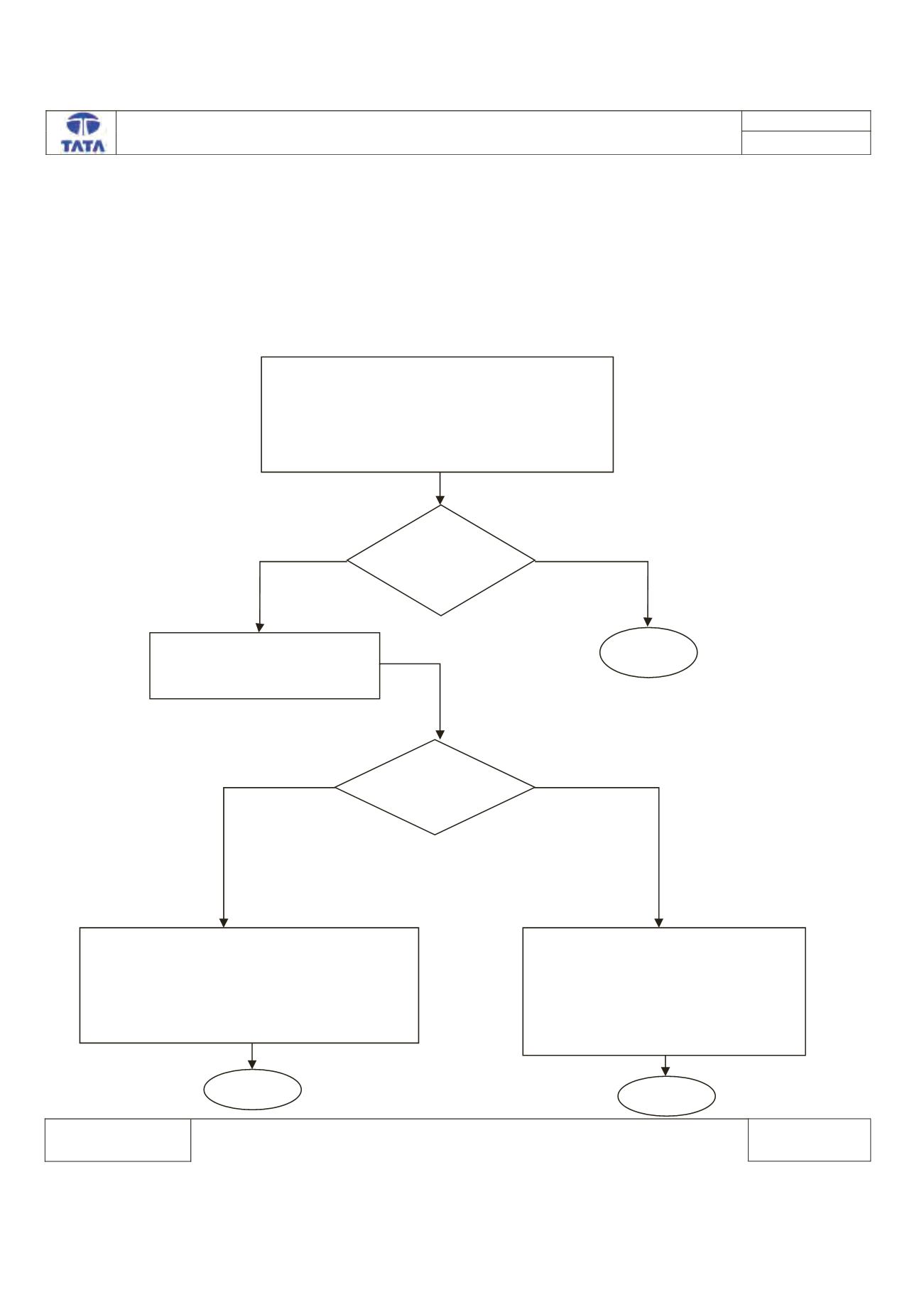
Trouble Shooting:-
Turn ON Ignition.
Connect the TML Diagnostic Tool.
Check the status of DTC’s (Memorized/Current)
Record the DTC & Clear DTC’s
Turn Ignition OFF & ON
Verify If DTC B190B -11 is present
Is DTC
B190B-11 is
Present?
Check for continuity between
Pin No.J1-10(GND) & J1-29 of
ECU Connector.
Is Continuity
Present?
OAT input is Short Circuit to Ground.
Rectify Fault at wiring Harness & wait for
20sec to recover the fault.
Clear the DTC. Verify the function of OAT
Sensor with multimeter & OAT value on LCD
display.
Clear the DTC from the ECU memory.
Turn Ignition OFF & ON.
Press the mode switch button one
time to show the OAT display value &
Check whether display is showing the
OAT value in Deg’ C.
^ƚŽƉ
^ƚŽƉ
z ^
EK
z ^
EK
^ƚŽƉ