


 1975 / 5157

yϭϬϰ KƐƉƌĞLJ /ŶƐƚƌƵŵĞŶƚ ůƵƐƚĞƌ
d dƌŽƵďůĞƐŚŽŽƚŝŶŐ ĂƚĂ
sĞƌƐŝŽŶ͗ ϭ͘ϯ
ĂƚĞ͗ ϮϬͲDĂƌĐŚͲϭϳ
Author: Balaji / Amar /
Nitin / Umapathi /
Deepak
Page: 94 of 138
Copyright ©
TATA MOTORS Ltd.
This document must not be used in any way, such as copying and redistributing to third parties, without the consent of author.
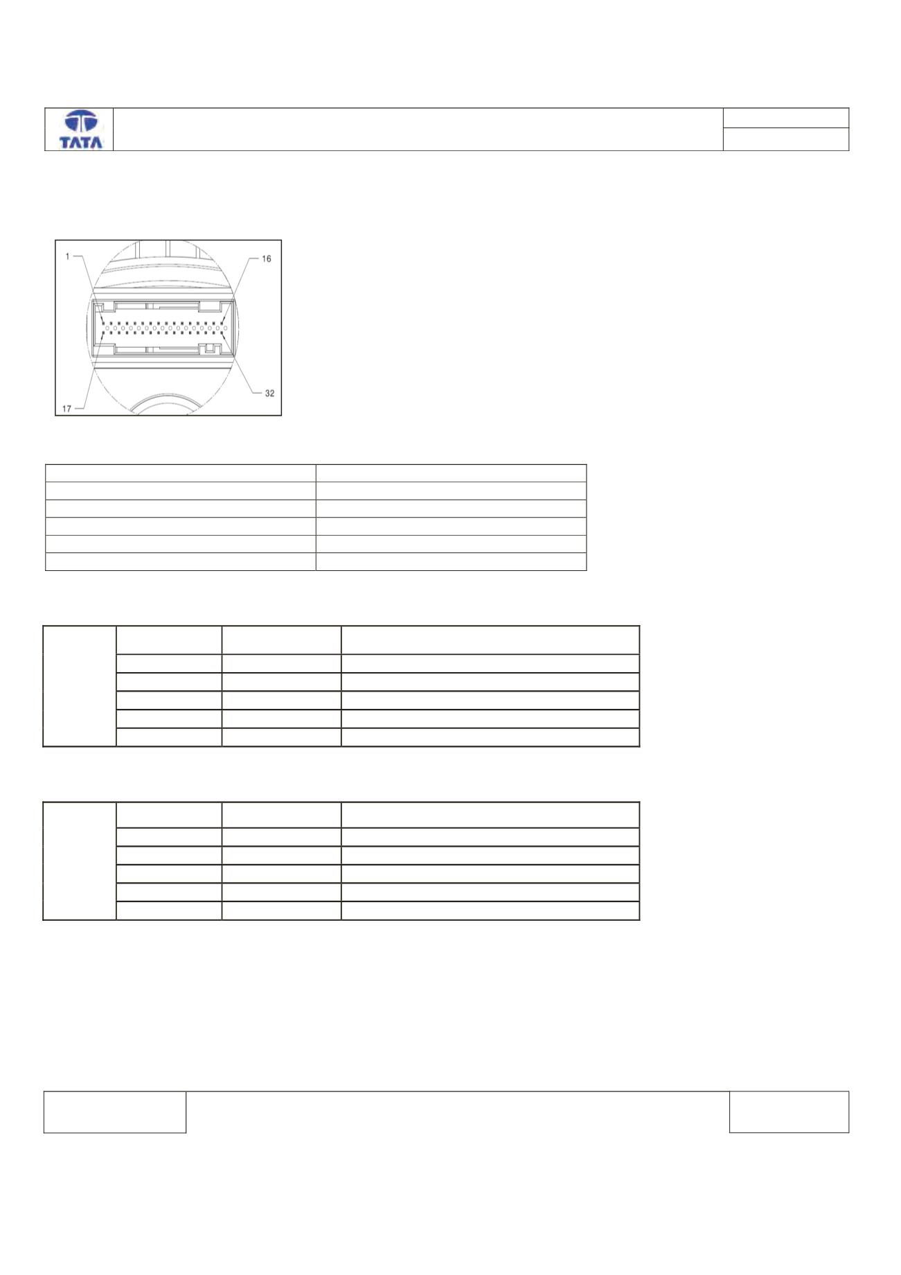
Connector View & Information:-
IPC ECU side connector diagram
ECU Pin assignment:-
Description
ECU pin
CAN_H chassis
6
CAN_L chassis
5
Battery
1
Ignition input
22
Battery ground
24
ECU Pin assignment (Applicable for Gasoline ECM)
Vehicle
Connector-1
Pin No.
Pin Name
Description
132
CAN_H
CAN High
144
CAN_L
CAN Low
116
Ign
Ignition
155,156
Vbat
Supply Voltage Battery
153,154
GND
Battery GND
ECU Pin assignment (Applicable for Diesel ECM)
Vehicle
Connector-1
Pin No.
Pin Name
Description
64
CAN_H
CAN High
40
CAN_L
CAN Low
23
Ign
Ignition
4,5,6
Vbat
Supply Voltage Battery
1,2,3
GND
Battery GND