


 1994 / 5157

yϭϬϰ KƐƉƌĞLJ /ŶƐƚƌƵŵĞŶƚ ůƵƐƚĞƌ
d dƌŽƵďůĞƐŚŽŽƚŝŶŐ ĂƚĂ
sĞƌƐŝŽŶ͗ ϭ͘ϯ
ĂƚĞ͗ ϮϬͲDĂƌĐŚͲϭϳ
Author: Balaji / Amar /
Nitin / Umapathi /
Deepak
Page: 113 of 138
Copyright ©
TATA MOTORS Ltd.
This document must not be used in any way, such as copying and redistributing to third parties, without the consent of author.
b) DTC should not be present in ECU memory.
Circuit Schematic Diagram:-
N.A
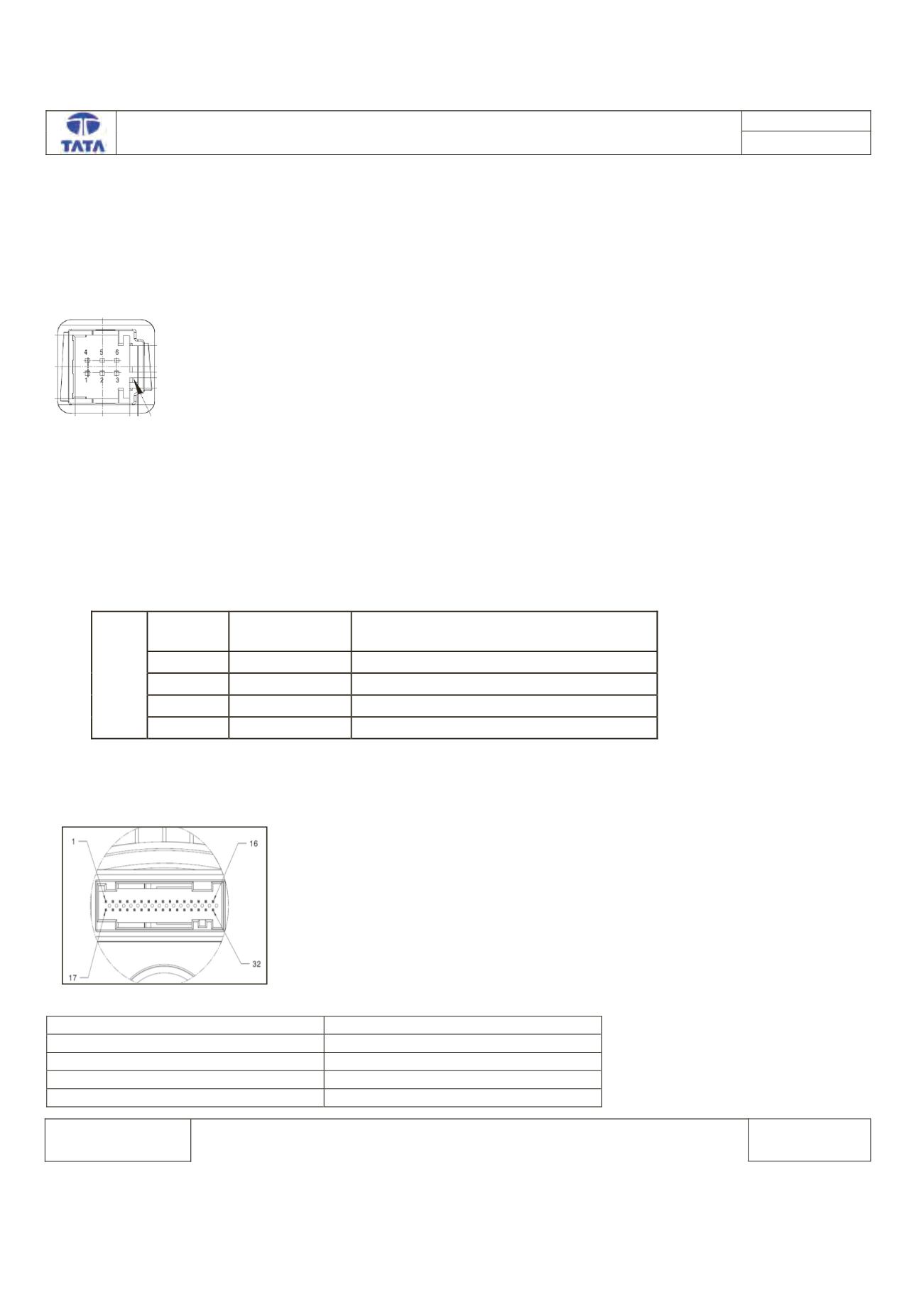
ESCL ECU side Connector:-
Component Location & Image:-
N.A
Connector Location:-
N.A
ESCL ECU Pin assignment:-
, D Z
WŝŶ EŽ͘
WŝŶ EĂŵĞ
ĞƐĐƌŝƉƚŝŽŶ
Ϯ
Eͺ,
E ,ŝŐŚ
ϯ
Eͺ>
E >Žǁ
ϲ
ͺ'E
sŽůƚĂŐĞ ĂƚƚĞƌLJ 'E
ϭ
s ďĂƚ
sŽůƚĂŐĞ ĂƚƚĞƌLJ WŽǁĞƌ
Connector View & Information: - IPC ECU side
IPC ECU side connector diagram
ECU Pin assignment:-
Description
ECU pin
CAN_H chassis
6
CAN_L chassis
5
Battery
1
Ignition input
22