


 1990 / 5157

yϭϬϰ KƐƉƌĞLJ /ŶƐƚƌƵŵĞŶƚ ůƵƐƚĞƌ
d dƌŽƵďůĞƐŚŽŽƚŝŶŐ ĂƚĂ
sĞƌƐŝŽŶ͗ ϭ͘ϯ
ĂƚĞ͗ ϮϬͲDĂƌĐŚͲϭϳ
Author: Balaji / Amar /
Nitin / Umapathi /
Deepak
Page: 109 of 138
Copyright ©
TATA MOTORS Ltd.
This document must not be used in any way, such as copying and redistributing to third parties, without the consent of author.
DTC’s confirmation:-
After rectification, ensure the following points using TML diagnostic tool before handing over to customer.
a) Check whether PEPS ECU is communicating with diagnostic Tool or not.
b) DTC should not be present in ECU memory.
Circuit Schematic Diagram:-
N.A
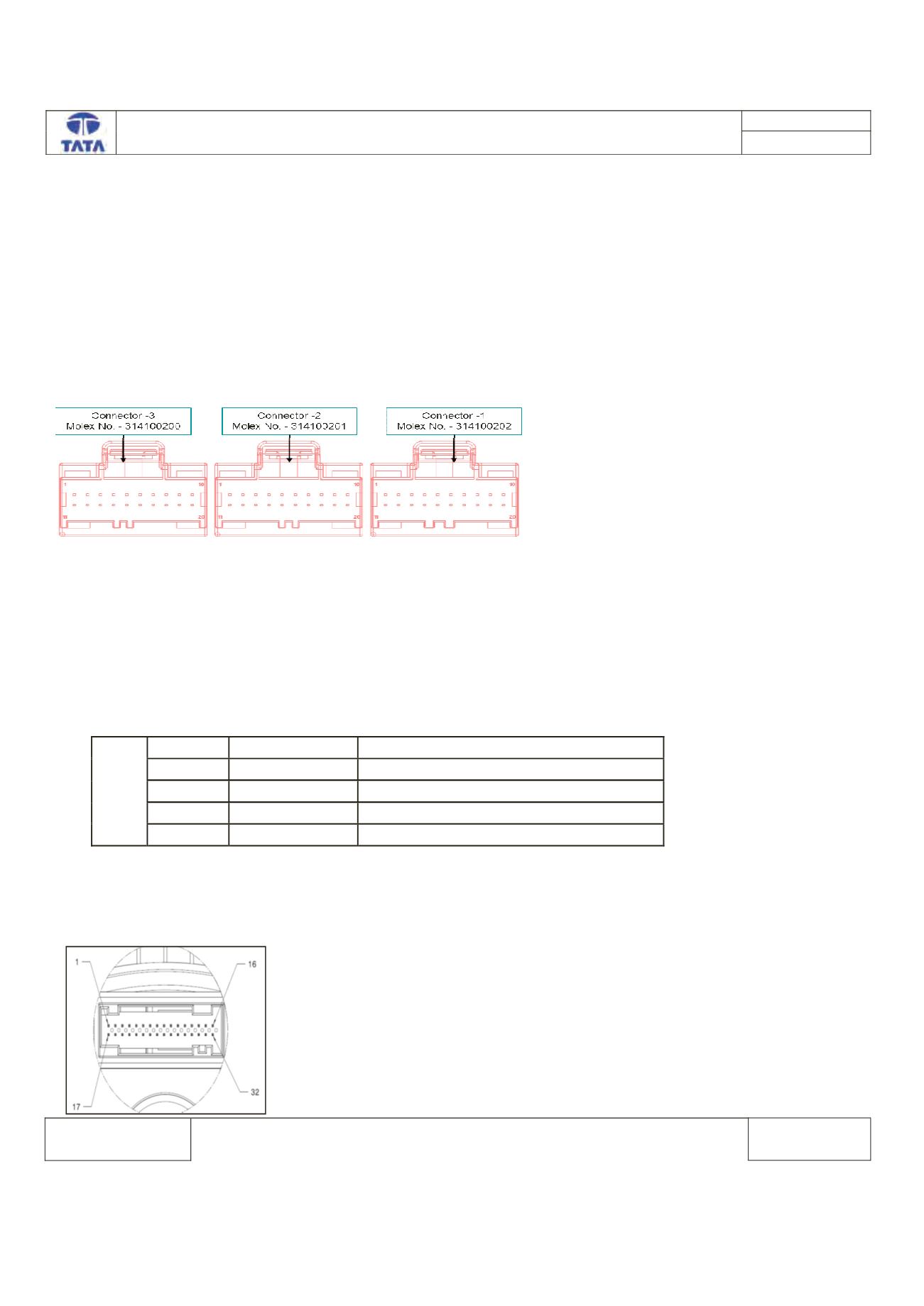
PEPS ECU side Connector:-
Component Location & Image:-
N.A
Connector Location:-
N.A
PEPS ECU Pin assignment:-
, D Z
WŝŶ EŽ͘
WŝŶ EĂŵĞ
ĞƐĐƌŝƉƚŝŽŶ
ϱ
Eͺ,
E ,ŝŐŚ
ϭϯ
Eͺ>
E >Žǁ
ϭ
W W^ͺ hͺ'ŶĚ 'E
ϭϬ͕ϵ s ďĂƚ
^ƵƉƉůLJ sŽůƚĂŐĞ ĂƚƚĞƌLJ
Connector View & Information:- IPC ECU side
IPC ECU side connector diagram:-