


 1984 / 5157

yϭϬϰ KƐƉƌĞLJ /ŶƐƚƌƵŵĞŶƚ ůƵƐƚĞƌ
d dƌŽƵďůĞƐŚŽŽƚŝŶŐ ĂƚĂ
sĞƌƐŝŽŶ͗ ϭ͘ϯ
ĂƚĞ͗ ϮϬͲDĂƌĐŚͲϭϳ
Author: Balaji / Amar /
Nitin / Umapathi /
Deepak
Page: 103 of 138
Copyright ©
TATA MOTORS Ltd.
This document must not be used in any way, such as copying and redistributing to third parties, without the consent of author.
DTC’s confirmation:-
After rectification, ensure the following points using TML diagnostic tool before handing over to customer.
a) Check whether HVAC ECU is communicating with diagnostic Tool or not.
b) DTC should not be present in ECU memory.
Circuit Schematic Diagram:-
Component Location & Image:-
N.A
Connector Location:-
N.A
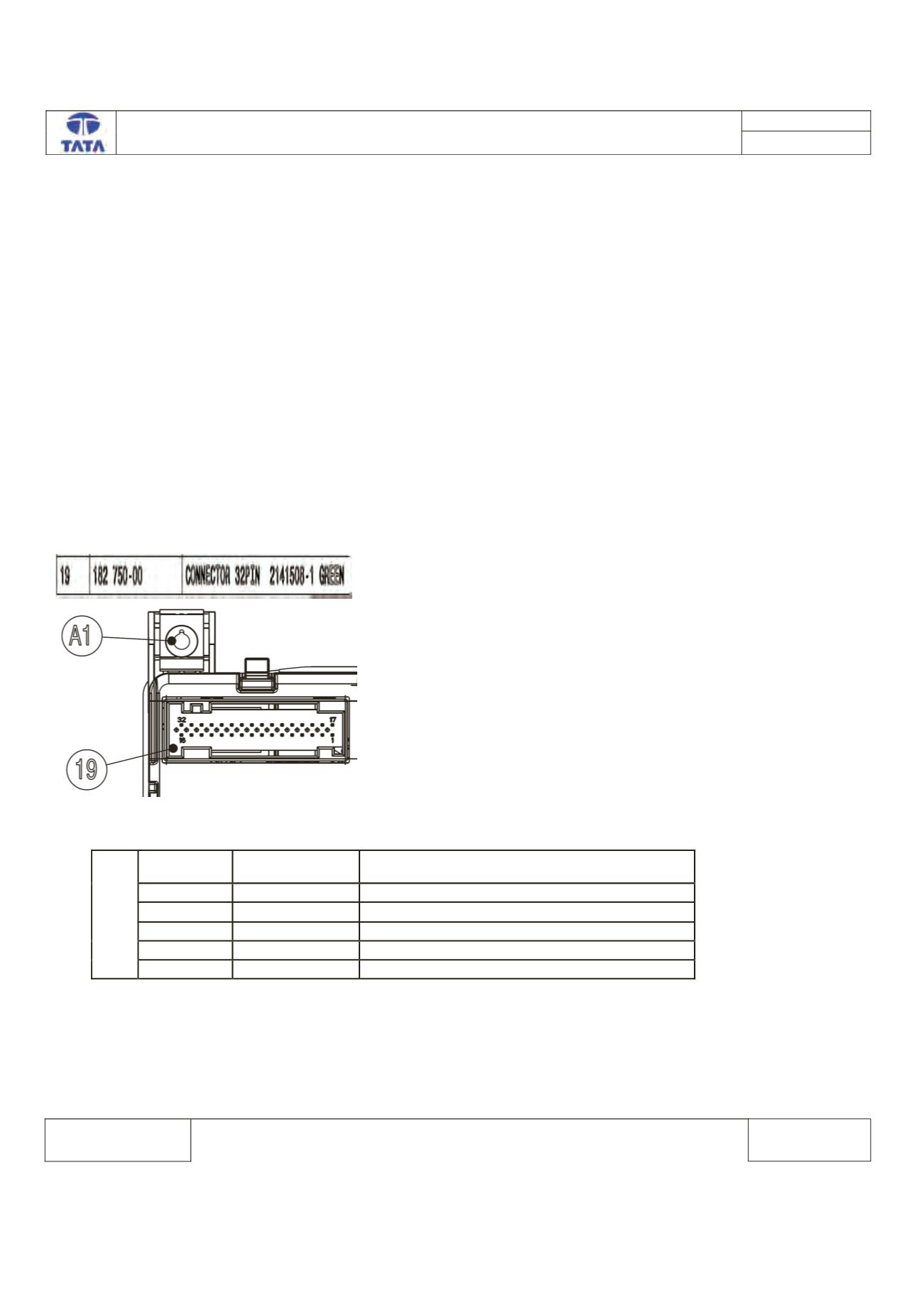
Connector View & Information:-
ECU side Connector
HVAC ECU Pin assignment
Pin No.
Pin Name
Description
24
CAN_H
CAN High
22
CAN_L
CAN Low
11
Ign
Ignition
15,16
Vbat
Supply Voltage Battery
1,2
GND
Battery GND